Case Studies in Precast and Model and Mold Making

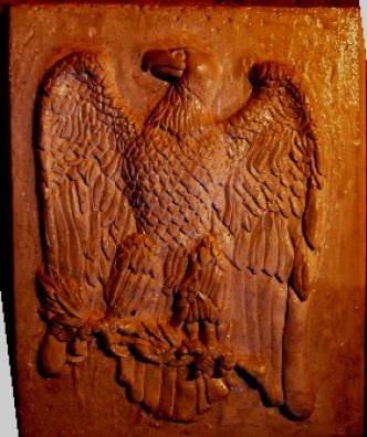
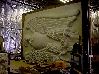
Case Study #1...The Eagle
or how I made an eagle over 4 meters tall from my lazy boy.
I was commissioned to create an eagle to be reproduced on four bridge abutment panels seventeen feet high for the Pennsylvania Department of Transportation in the summer of 2008. It started with an oversimplified architects sketch which I worked from in pen and ink for the original submission, shown at left. This drawing was approved and I began work on the model.
The full precast panel was to be seventeen feet tall and the eagle itself would be thirteen and one half feet in height. It was also specified that the highest point on the eagle would be nine inches in depth over the background. I contracted privately for this and had to work within the confines of my home. Fortunately, there are methods for scanning an image three dimensionally and then scaling it to any desired size. Consequently, I was lucky enough to fulfill this commission in the comfort of my favorite lounge chair while watching Netflix.
The method used for accurate scaling was simple enough. After determining the eagle proper was to be 13'-6" high, an easy scale was 1:1728. That is, one inch would equal one foot (12 to 1 in 3 dimensions =1728). Therefor my model would be about 13 1/2" high and 3/4" at the highest point.
The first stage involved making a rough model in clay approximating 3/4 inches in depth. Since it was specified the final cast could not exceed 9" in depth, my clay model was screeded using two standard strips of 3/4" plywood. Working at such a scale, I felt that my manipulation of clay would not achieve sufficient clarity of detail. So I only made an approximation of the model I needed and proceeded to make a temporary rubber mold from the clay into which I could cast a new plaster model to replace the clay one. This is a technique I use frequently, since plaster can be easily carved to achieve the same detail and smoothnesses where desired as marble, where you might spin your wheels on clay but with little control over your model..
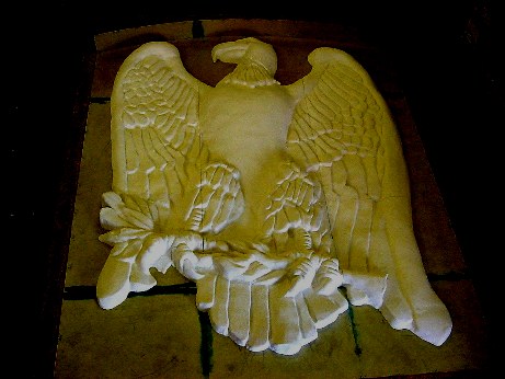
The Plaster model
Stage 2 involved completing the plaster model, occasionally submitting a photo to be sure I was still on the desired track according to PDOT and the architect. Unfortunately sometimes glitches occur . In this case they determined even after the model was complete that the contract documents had changed and they wanted the following two changes: the eagle's chest was not to have feathers, and the wings feather patterns were to be more stylized.
I was paid for these change orders, and the easiest way to proceed was to again make a rubber mold from this model, and then fill in the feather depressions with plaster on the chest in the rubber mold and cast a new plaster model from that.
I was paid for these change orders, and the easiest way to proceed was to again make a rubber mold from this model, and then fill in the feather depressions with plaster on the chest in the rubber mold and cast a new plaster model from that.
The Final Plaster Model

This was the new and finally approved model which was sent to be scanned and enlarged.
The process involved computer driven carving in foam of the full size model.
The process involved computer driven carving in foam of the full size model.
Images below of the computer aided machining of the full size foam model.
The Mold
The mold for the final precast concrete cast was created with about 25 gallons of a rubber molding compound. The rubber requires a mother mold, in this case of concrete, to give the complete mold assembly a flat bottom and support for the rubber inner mold.
In November 2008 the four panels were installed, one shown below.
In November 2008 the four panels were installed, one shown below.

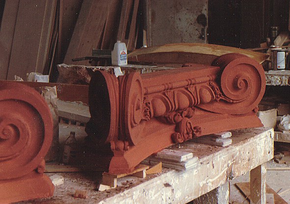
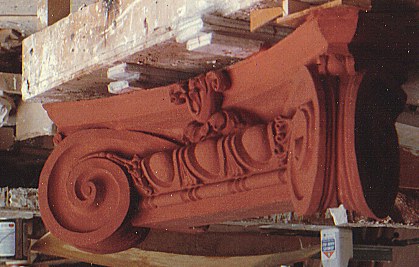
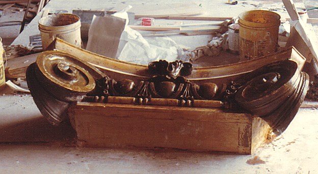
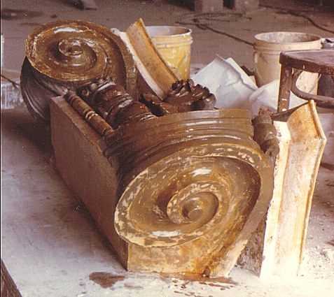
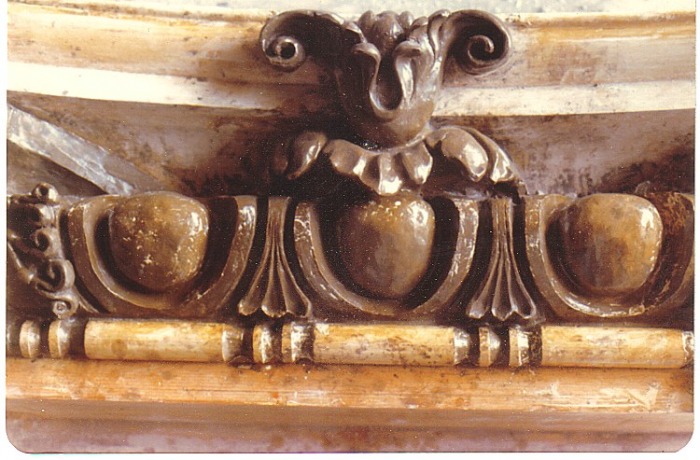
National Institute of Health Column Capital Reproduction Washington D.C, 1984
Case study #2 NIH column Caps for new addition
NIH built several additional buildings in an area where the other surrounding buildings incorporated ornamental column capitals of terra cotta created earlier in the 20th century. It was required to reproduce the design without being able to have direct access to any of the originals. But we were able to take photographs from an adjacent building and strategically, from directly below. The upper portion of the capital has a profiled band on a radius. It was possible to measure the chord of this arc by counting the number of bricks above that it spanned. The photo taken from below, once that chord was known, could be used to estimate the rise, or the distance the ends of the arc extended from the brick. The rise and chord can in turn yield the radius, the desired figure by the equation R(radius)=(ch squared +rise squared)/ (8* rise).
NIH built several additional buildings in an area where the other surrounding buildings incorporated ornamental column capitals of terra cotta created earlier in the 20th century. It was required to reproduce the design without being able to have direct access to any of the originals. But we were able to take photographs from an adjacent building and strategically, from directly below. The upper portion of the capital has a profiled band on a radius. It was possible to measure the chord of this arc by counting the number of bricks above that it spanned. The photo taken from below, once that chord was known, could be used to estimate the rise, or the distance the ends of the arc extended from the brick. The rise and chord can in turn yield the radius, the desired figure by the equation R(radius)=(ch squared +rise squared)/ (8* rise).
Next step: model
The model was begun as a multi media project, with a base of wood, plaster cornice, and clay details. The radial band part on top was run in plaster independently and then cut to fit as needed and assembled. The process of running plaster is detailed elsewhere. The Volutes and the egg and dart pattern are clay, as is the central flower.
The mold
Regretfully, I have no surviving photos of the mold, if there ever were any. It was a multi-part construct where the the area occupied by the dart pattern and flower was rubber, the areas of the side volutes and radial band, plaster, and all the various parts held in place by a concrete mother mold. So you'll have to take my word the following imitation terra cotta precast concrete pieces cast were produced from such a mold.
The precast product
The terra cotta appearence required was achieved with a design mix of 6% mineral oxide pigment to cement ratio. In addition, to achieve greater uniformity in appearance, additional processing included an acid wash for etching and a surface coating applied composed of grey cement, a bonding agent, and the same pigment. Below, the new precast concrete faux terra cotta in a staging area nearing process completion. To the right, a portion of the image has been inverted to help better visualize the final appearance in the proper orientation.